

HTF
The HTF test loop was erected in 1997 and it is an ideal facility for evaluating parabolic-trough collector components under real solar energy operating conditions.
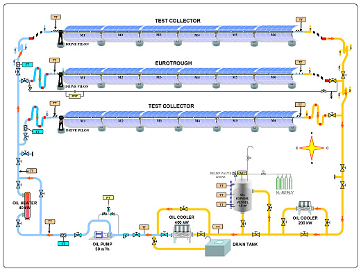
The facility consists of a closed thermal-oil circuit connected to several solar collectors of 75-m long connected in parallel (up to three collectors can be installed in parallel), being able to operate only one at a time. The east-west rotating axis of the solar collectors increases the number of hours per year in which the angle of incidence of the solar radiation is less than 5º. The thermal oil used in this facility (Syltherm 800) has a maximum working temperature of 420ºC and a freezing point of -40ºC.
The facility’s oil circuit, which has a maximum working pressure of 20 bar, is made up of the following elements:
- 1-m3-capacity oil expansion tank, with automatic nitrogen inertization
- Oil circuit sump tank.
- Mechanical-draft oil cooler, with air speed control and 400-kW maximum cooling
- Centrifugal oil pump, with a flow rate of up to 8.3 liters per second
- Two 40-kW electric oil heaters
The first EUROtrough collector prototype developed by an European consortium with the financial aid of the European Commission was installed and evaluated under real working conditions at this facility in 1998 The facility is appropriately instrumented for qualifying and monitoring of the follow-ing components:
- New designs of parabolic-trough collectors (up to 75 m long)
- Parabolic-trough collector mirrors
- Parabolic-trough collector absorber tubes
- New designs of ball-joints or flexholes for connecting parabolic-trough collectors in the solar fields.
- Solar tracking systems.
Main activities are currently related to study the optical and thermal performance of complete para-bolic-trough collectors (optical efficiency, IAM coefficient, and global efficiency/heat losses) and receiver tubes.